
Wear in Centrifugal Pumps
Centrifugal pumps are sometimes used in environments where the pumped product contains suspended solids. While some pumps are specifically designed for solid handling or slurry applications, normal centrifugal pumps do not contain features to prevent performance degradation from the impact of solids.
There are a few key signs that a conventional centrifugal pump is suffering from erosive and abrasive wear. Here are assessment and mitigation strategies to be considered and applied when this occurs.
Particles are a problem in a centrifugal pump due to the way the machine adds velocity to the liquid as it passes up the impeller channels. In general, the higher the speed at the tip of the impeller, the more energy that is imparted to any particle that is suspended within the liquid. This energy can then cause damage to anything it impacts.
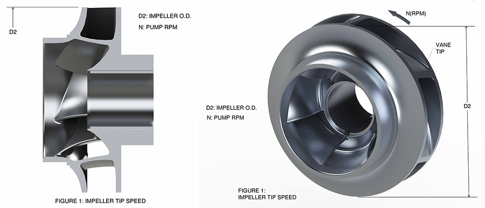 Image 1. Particle velocity is directly associated to the tip speed of the impeller. (Images courtesy of Hydro, Inc.)
In general terms, the material loss by erosion is determined by the velocity of the particle cubed (Equation 1).
Equation 1:
Erosion = XC3
C is the velocity of the particle
X is a coefficient based on the liquid
being pumped
The velocity of the particle is directly associated to the tip speed of the impeller (Image 1). Lowering the tip speed of a machine has a significant impact on particle velocity and, thus, the erosive energy.
Tip Speed= πD2n/60
In particular, this affects particles exiting the impeller with the high velocity impact onto the pump volute lips, causing erosive damage.
As a high-energy particle passes from the impeller onto the volute lip, a very particular pattern of damage occurs. The damage is generally concentrated at the intersection of the casing volute lip and the side wall of the casing. Particles that impact the center of the volute lip are swept away into the mean streamline flow, and the time they are in contact with the lip is limited (Image 2).
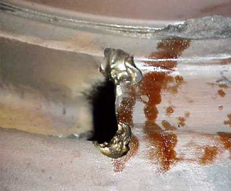
Image 2. Illustration of wear at the volute lip
The particles that impact the volute lip close to the side wall become influenced by the double boundary layer interface that exists between the lip and side wall. These particles are not quickly passed into the mean streamline flow and begin to spin (Image 3).
Image 3. Representation of particle movement illustrating near-wall vs. mid-stream flow
Other areas are also susceptible to wear and are generally associated with the fine clearance of the wear ring annulus. There are two types of abrasive/erosive wear that increase the wear ring clearance and deteriorate pump performance.
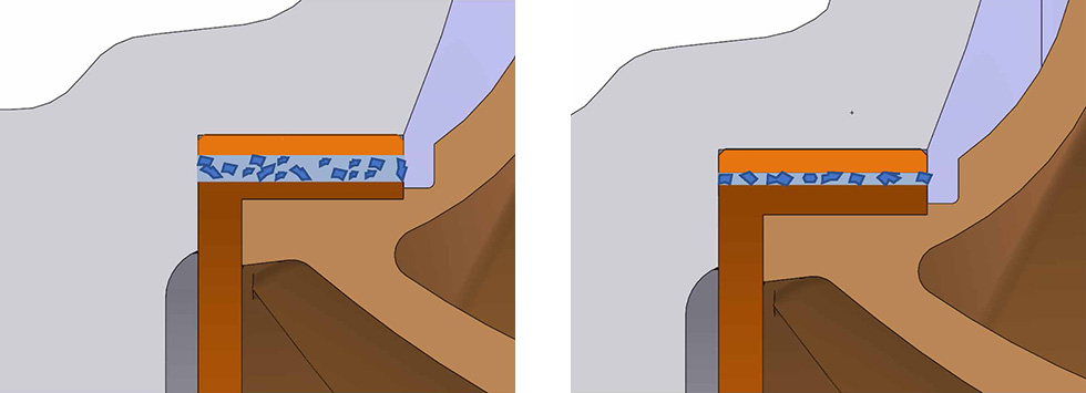 Image 4 (left). Particles pass across the wear ring clearance driven by differential pressure and their shape and direction impact onto the wear ring surfaces increasing the clearances. Image 5 (right). If the wear ring clearances are smaller than the maximum particle size, material is removed from the clearance.
Wear rings also play a significant part in another common form of wear that occurs in the volute casing side walls. One of a wear rings’ primary functions is to provide a restrictive annulus between different pressure regimes within a centrifugal pump. Because of this function, one side of the wear ring operates at higher pressure than the other. The differential pressure across the ring annulus drives the fluid across wear ring clearance.
This effect has stiffening properties that improve the rotordynamics of the machine. Within an erosive environment this can cause a particular wear pattern of damage. As the liquid exiting the wear ring annulus jets into the low pressure passage carrying higher energy particles, with it the particles impact the casing side wall and cut into the pressure boundary. This is known as Taylor vortex damage.
Tactics for Limiting Wear
Limiting tip speeds on services where particles may be present within the pumped fluid limits damage. If the tip speed cannot be limited, choose a machine that has a high tip clearance between the impeller outside diameter and the volute lip. This gives time/distance/velocity the chance to act on any particles, thus reducing their velocity before they impact the casing.
Modify the volute lips. By profiling the volute lips into a horseshoe shape, it is possible to limit the wear seen at the intersection between the lip and casing side wall. The large, smooth radius on the lip means that the consequence of the double boundary layer that holds the particles and causes them to spin due to the passing flow is minimized as the particles are forced into the mean flow stream by the geometry of the radius and cannot be stuck in corner intersections (Image 6).
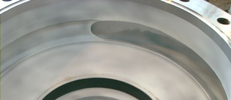
Image 6. Volute lip modification to ease damage
Coatings can be helpful in combatting abrasive wear, but it requires a skillful eye to ensure the right type of coating is applied in the right areas based on an assessment of the damage that is observed. Coating with a high bond strength and a high hardness when applied in conjunction with the other techniques mentioned in this article can be successful in limiting damage.
Particles present in centrifugal pump liquids can cause damage and performance degradation. Some damage is still inevitable, but using modifications to geometry, combined with hard coatings, increases pump life and reliability.